Analytical & Experimental Research of Rapid Dual Thread Screw Implant
Dr. Yhoda Carmeli & Amir Yardeni Mechanical engineer
Introduction
As the popularity of using implants in dental restorative procedure gains momentum, there is a need to find innovative dental implant, which can effectively transfer the loads and provide the necessary stabilization into jawbone.
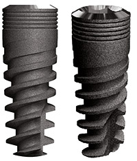
This paper presents the development results of a novel implant with a Dual Thread Screw as shown in Fig.1.
This approach allows obtaining a high reinforcement of the implant in the jawbone by a reduction of the drilling bone volume along with an additional gain of primary surface contact relatively to classical implants.
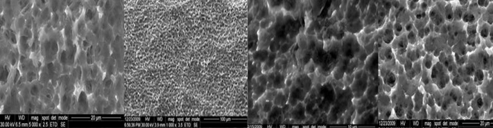
To prove the concept, analytical models and xperiment tests were carried out during the development of an implant with Dual Thread Screw . The analytical calculations are based on Finite Element Model, while the experiment tests were done on an artificial bone made of Fiberglass and Structural foam, which represents the bone mechanical properties. These unique experimental tests which have been chosen, since the clinical tests evaluations on animals are not efficient. The animal has different dental jaw structure and it requires a lot of time to get the results.
Dental Implant Description
The unique dental Implant, shown in Fig. 1, uses dual threads with conical core with five rings at the implant interface area with the cortical bone and dual thread thick groves at the cancellous. This unique design allows facilitating the transfer of occlusal forces to the
greatest surface area of the bone-implant interface for favorable load distribution. Also it reduces the amount of bone removed by using a novel drilling procedure.
Experimental Method
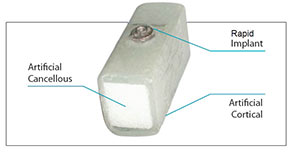
Force-displacement tests have been carried out on Classical Cylindrical Implant and implant both have diameter of 4.2 mm and 13 mm in length. The implants have been inserted in an artificial bone specimen shown in Fig. 2, the cross section dimensions of this specimen are of a typical mandible as is shown in Fig. 2. An axial load was applied onto the implant head until failure was reached. During the static tests the force-displacement curves were recorded and axial stiffness has been calculated.
Experimental Results
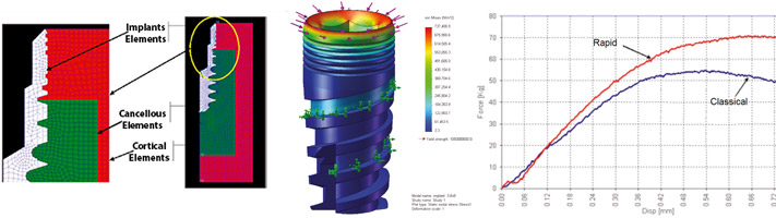
The experimental tests showed that the implant could carry higher axial load compared to classical cylinder implants, as shown in figure 4. It is also shown that implant has higher stiffness then the classical cylindrical implant. The stiffness of the implants is compatible with measured axial stiffness of 180 Kg/mm Analytical Method Finite Element Model (FEM) of an implant installed in a standard jawbone cross section has been built using NASTRAN FEM software. The aim of this study was to evaluate the influence of implant versus classical cylindrical implants on the stress intensity and stress distribution due to axial load. Two analytical models were built for the identical specimen types described above. The Implant stress distribution at the bone cross section was calculated.
The FEM model of the dental implant bone system used 2-D Plate elements; the model is symmetrical since only axial (vertical) load had been analyzed, as is shown in Fig. 4.
.
Analytical Results
The analytical calculations showed that the implant have favorable stress distribution over the classical cylindrical implant. The maximal shear stress level at the cortical jawbone with implant is 15% to 25% lower compared with a classical cylindrical implant, which plots the max shear stress distribution in the cortical bone under an axial load of 40 Kg for the both type of implants.
.
Discussion & Conclusions
The experimental tests showed that implant achieved the highest vertical load capability compared with a classical cylindrical implant. The unique tests experiments method evaluates in this study provided short development time by using artificial bone specimen.
These experiments were done with a background of analytical calculations. The lower shear stress values at the cortical bone evaluate for the implant compared with the classical cylindrical implants provides the advantage of the implant regarding on carrying higher loads and increasing life time of the implant. This phenomenon is mostly due to the innovative implant geometry and bone drilling method.
References
- Lawrence B. Lum,A Biomechanical Rationale for the use of Short Implants. Journal of Oral Implantology Vol. XVII/ No. Tow/1991 pp126-131
- Borchers L. Relchart P.“Three – dimensional stress distribution around a dental implant at different stages of interface development”.
- J. Dent Res 1983 62(2):156-159 Kitoh, M; Matsushita, Y.; Yamautue, S; Ikedda, H.; and Suetsugu, T. The Stress Distribution of Hydroxyapatite Implant Under Vertical Load by the Two-Dimensional Finite Element Method. Journal of Implantol 14:65-71 Dechow P.C. Naill
- G.A. Schwartz-Dabney C.L. and Ashman R.B., “Elastic properties of the human supraorbital and mandibular bone”. Am J Phys Anthropol 90, pp 291-306. 1993.